PEEK (polyetheretherketone) stands as one of the most advanced engineering thermoplastics available for precision CNC machining. With exceptional thermal stability, outstanding chemical resistance, and impressive mechanical properties, PEEK has become the material of choice for demanding applications across aerospace, medical, and industrial sectors. This comprehensive guide explores everything you need to know about PEEK CNC machining—from material properties to design considerations and industry applications.
Understanding PEEK Material Properties
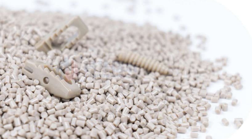
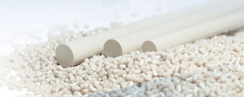
PEEK is a semi-crystalline thermoplastic polymer that offers an exceptional combination of properties that make it ideal for precision machining applications. Before diving into the machining process, it’s essential to understand what makes this material so valuable for high-performance components.
Key Mechanical Properties
PEEK delivers outstanding mechanical strength with tensile values ranging from 90-100 MPa and excellent dimensional stability even under load. The material maintains its mechanical properties at temperatures up to 260°C (500°F), making it suitable for applications where other plastics would fail. Its exceptional wear resistance and low coefficient of friction make it ideal for moving parts and bearings.
Chemical and Environmental Resistance
One of PEEK’s most valuable characteristics is its remarkable chemical resistance. The material withstands exposure to most acids, bases, and organic solvents without degradation. It’s also hydrophobic, meaning it absorbs minimal moisture, and exhibits extremely low outgassing in vacuum environments. These properties make PEEK particularly valuable in aerospace, semiconductor, and medical applications where material stability is critical.
| Property | Unfilled PEEK | 30% Glass Filled | 30% Carbon Filled |
| Tensile Strength | 90-100 MPa | 110-130 MPa | 130-150 MPa |
| Heat Deflection Temp | 160°C | 315°C | 288°C |
| Continuous Use Temp | 250°C | 250°C | 260°C |
| Elongation at Break | 30-50% | 2-5% | 1-2% |
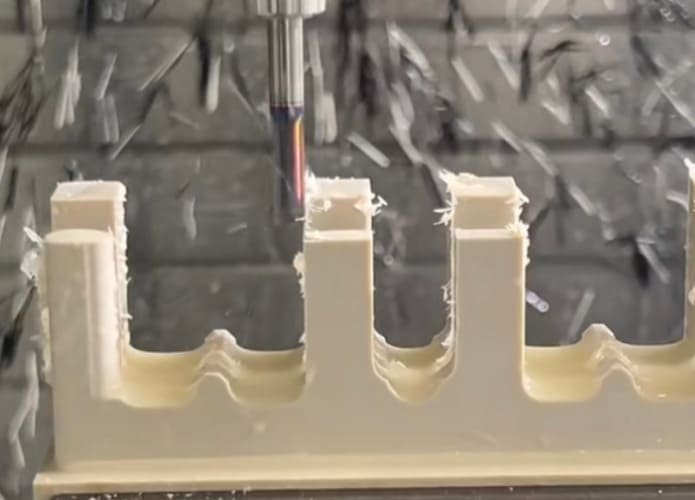
Why Choose CNC Machining for PEEK Components?
While PEEK can be processed through various manufacturing methods including injection molding and 3D printing, CNC machining offers distinct advantages for many applications, particularly when precision and material properties are paramount.
Advantages of PEEK CNC Machining
- Exceptional dimensional accuracy (tolerances as tight as ±0.001″)
- No material property compromise (unlike some 3D printing methods)
- Ability to create complex geometries with fine details
- No tooling costs compared to injection molding
- Economical for low to medium production volumes
- Faster turnaround for prototypes and small batches
- Ability to machine from solid stock with consistent properties
- Superior surface finish capabilities
Limitations to Consider
- Higher material costs compared to commodity plastics
- Less economical for very high volumes than molding
- Potential for internal stress if machining parameters aren’t optimized
- Limited design freedom compared to additive manufacturing
- Material waste from subtractive process
Pro Tip: For components requiring both complex internal geometries and tight tolerances, consider a hybrid approach—using injection molding for near-net shapes followed by precision CNC machining for critical features.
Key Considerations for Successful PEEK Machining
While PEEK offers excellent machinability compared to many engineering plastics, achieving optimal results requires attention to several critical factors. The following considerations will help ensure successful outcomes when machining PEEK components.
Tool Selection
For optimal PEEK machining, use sharp carbide tools with polished cutting edges. Single or double-fluted end mills work well for most operations, while PCD (polycrystalline diamond) tools are recommended for high-production environments. Maintain positive rake angles between 0-5° to reduce cutting forces and heat generation.
Speeds and Feeds
PEEK machines best with moderate to high cutting speeds (500-1000 SFM) and conservative feed rates. Start with cutting speeds 20-30% lower than those used for aluminum and adjust based on results. For filled grades like GF30 or CF30, reduce speeds by an additional 10-15% to account for the abrasive nature of the fillers.
Cooling and Heat Management
Effective cooling is critical when machining PEEK to prevent heat buildup that can affect dimensional stability. Use compressed air or water-soluble coolants to maintain temperature control. For medical or semiconductor applications where contamination is a concern, dry machining with compressed air cooling is recommended.
Fixturing and Workholding
Proper workholding is essential for achieving tight tolerances when machining PEEK. The material’s relatively low stiffness compared to metals means that inadequate support can lead to deflection and dimensional issues. Use vacuum tables, custom fixtures, or soft jaws to distribute clamping forces evenly and minimize distortion. For thin-walled parts, consider sacrificial supports that can be removed after machining.
Design Guidelines for PEEK CNC Machining
Optimizing your design for PEEK CNC machining can significantly impact both part performance and manufacturing costs. These guidelines will help you create designs that leverage PEEK’s exceptional properties while ensuring manufacturability.
Wall Thickness and Feature Sizing
When designing PEEK components, maintain minimum wall thicknesses of 0.040″ (1mm) for unfilled grades and 0.060″ (1.5mm) for filled grades to ensure structural integrity. For deep pockets, aim for a depth-to-width ratio of no more than 4:1 to allow for proper tool access and minimize deflection during machining.
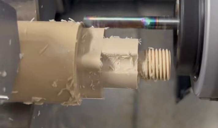
For holes and bores, maintain a minimum diameter of 0.020″ (0.5mm) for unfilled PEEK and 0.030″ (0.75mm) for filled grades. When designing threaded features, consider that PEEK threads have approximately 80% of the strength of comparable metal threads, so adjust sizing accordingly or consider thread inserts for high-load applications.
Corner Radii and Transitions
Incorporate internal corner radii of at least 0.020″ (0.5mm) to reduce stress concentration and improve machinability. Sharp internal corners require additional machining time and can introduce stress points in the finished part. Gradual transitions between different wall thicknesses help maintain dimensional stability and reduce internal stress.
Tolerancing Considerations
While PEEK can be machined to tight tolerances, being realistic about tolerance requirements can significantly impact costs. Standard tolerances of ±0.005″ (0.127mm) are readily achievable, while precision tolerances of ±0.001″ (0.025mm) require additional care and may increase costs. Consider specifying tighter tolerances only for critical features while using standard tolerances elsewhere.
For filled grades of PEEK, be aware that the presence of glass or carbon fibers can affect achievable surface finishes and edge definition. Design accordingly by specifying appropriate surface finish requirements and allowing slightly larger radii on edges and corners.
Design Tip: When designing assemblies that include both PEEK and metal components, account for PEEK’s higher thermal expansion coefficient (approximately 3 times that of aluminum and 7 times that of steel) to prevent interference issues across your operating temperature range.
Common Challenges and Solutions in PEEK Machining
Despite PEEK’s excellent machinability, certain challenges can arise during the manufacturing process. Understanding these potential issues and their solutions will help ensure successful outcomes for your PEEK components.
How do you prevent internal stress and warping?
Internal stress in PEEK parts can lead to warping or dimensional changes, particularly in complex geometries. To minimize this issue:
- Implement annealing before final machining operations (typically 2-4 hours at 200°C followed by slow cooling).
- Use symmetrical material removal strategies to balance internal stresses.
- Consider roughing operations followed by a rest period before finishing cuts.
- Machine from stress-relieved stock when possible.
How do you achieve optimal surface finish?
Surface finish quality can be critical for many PEEK applications, particularly in medical or fluid-handling components. To achieve excellent surface finishes:
- Use sharp, polished cutting tools with appropriate geometries.
- Implement high spindle speeds with light finishing passes.
- Consider diamond-polished tools for final finishing operations.
- For filled grades, expect slightly rougher finishes due to fiber exposure.
How do you manage tool wear with filled PEEK grades?
Glass and carbon-filled PEEK grades can be highly abrasive, leading to accelerated tool wear. To manage this challenge:
- Use harder cutting tools (carbide minimum, PCD preferred for production runs).
- Reduce cutting speeds by 10-15% compared to unfilled PEEK.
- Implement more frequent tool changes based on surface finish requirements.
- Consider specialized coatings like diamond-like carbon (DLC) for extended tool life.
Post-Processing and Finishing Options for PEEK
After CNC machining, PEEK components often benefit from various finishing operations to enhance their performance, appearance, or functionality. These post-processing techniques can significantly impact the final part quality and suitability for specific applications.
Surface Treatments
Common surface treatments for PEEK include bead blasting for a uniform matte finish, polishing for reduced friction, and specialized texturing for improved grip or aesthetic purposes. For medical applications, electropolishing can create ultra-smooth surfaces that resist bacterial adhesion.
Thermal Processing
Annealing is the most common thermal post-processing technique for PEEK, helping to relieve internal stresses and improve dimensional stability. Typical annealing cycles involve heating to 200-220°C for 2-4 hours followed by controlled cooling at 10-15°C per hour until reaching room temperature.
Assembly Preparation
PEEK components often require preparation for assembly with other parts. Options include ultrasonic cleaning for removing machining residues, plasma treatment for improving adhesion properties, and installation of threaded inserts for stronger mechanical connections.
Surface Finish Comparison
| Finish Type | Surface Roughness | Appearance | Best Applications |
| As-Machined | 32-63 μin Ra | Tool marks visible | General purpose, non-critical surfaces |
| Bead Blasted | 60-125 μin Ra | Uniform matte | Improved grip, visual uniformity |
| Polished | 8-16 μin Ra | Smooth, semi-gloss | Fluid flow, reduced friction |
| Diamond Polished | 2-8 μin Ra | Mirror-like | Medical implants, optical applications |
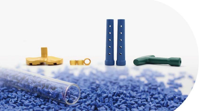
Industry Applications for PEEK CNC Machined Components
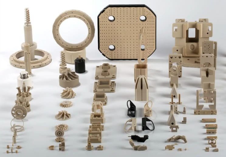
PEEK’s exceptional combination of properties makes it ideal for demanding applications across multiple industries. Understanding how PEEK components perform in various sectors can help inform material selection and design decisions for your specific requirements.
Aerospace & Defense
- Lightweight structural components
- Electrical insulators and connectors
- Bearing components and bushings
- Fuel system components
- Thermal insulation elements
PEEK’s high strength-to-weight ratio, flame resistance, and stability in extreme environments make it ideal for aerospace applications where weight reduction and reliability are critical.
Medical & Dental
- Spinal implants and cages
- Dental abutments and frameworks
- Surgical instruments
- Drug delivery devices
- Medical imaging components
PEEK’s biocompatibility, radiolucency, and bone-like mechanical properties have made it a revolutionary material in the medical field, particularly for implantable devices and precision surgical tools.
Semiconductor & Electronics
- Wafer handling components
- Test sockets and fixtures
- Vacuum chamber components
- Electrical insulators
- Chemical processing equipment
The semiconductor industry relies on PEEK’s exceptional chemical resistance, dimensional stability, and low outgassing properties for components used in demanding clean room environments and chemical processing applications.
Oil & Gas
In the oil and gas industry, PEEK components have revolutionized downhole tool performance by withstanding extreme temperatures (up to 260°C) and pressures while resisting corrosive environments. CNC machined PEEK parts including valve seats, seals, and bushings have demonstrated service lives up to 5 times longer than traditional materials, resulting in significant cost savings through reduced maintenance and downtime.
PEEK vs. Other High-Performance Polymers
While PEEK offers exceptional performance, other high-performance polymers may be more suitable for specific applications. Understanding how PEEK compares to alternatives can help you make the optimal material selection for your machined components.
| Property | PEEK | PEI (Ultem) | PPSU (Radel) | PAI (Torlon) |
| Max Continuous Use Temp | 260°C | 170°C | 180°C | 260°C |
| Chemical Resistance | Excellent | Good | Very Good | Good |
| Mechanical Strength | Very High | High | Moderate | Highest |
| Machinability | Excellent | Very Good | Good | Challenging |
| Relative Cost | High | Moderate | Moderate | Very High |
When comparing these materials for CNC machining applications, PEEK often provides the best balance of performance and machinability. However, PEI (Ultem) may be preferable when flame retardancy and lower cost are priorities, while PAI (Torlon) offers superior wear resistance for bearing applications at the expense of more challenging machinability.
Conclusion
PEEK CNC machining represents the intersection of advanced material science and precision manufacturing. By understanding the unique properties of PEEK, implementing proper machining strategies, and following design best practices, engineers and manufacturers can create components that perform exceptionally in the most demanding environments.