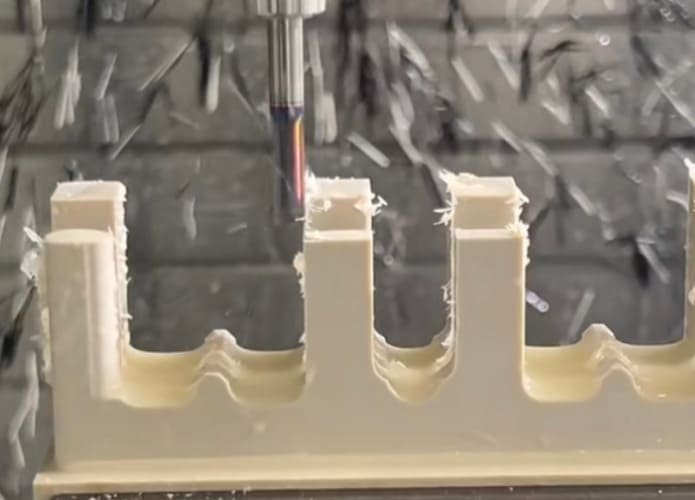
Machining components with thin walls presents significant challenges for even the most experienced manufacturing professionals. These delicate features, common in aerospace, automotive, and medical industries, require specialized approaches to maintain dimensional accuracy and surface quality. When thin walls deform through warping or develop chatter marks, the consequences range from costly rework to complete part rejection. This comprehensive guide examines the causes of these issues and provides practical strategies to achieve precision results when machining thin walls.
Understanding the Challenges of Machining Thin Walls
Thin-walled components, typically defined as having wall thicknesses below 1/32″ (0.794mm), present unique manufacturing challenges. These parts must maintain strict dimensional tolerances while being inherently susceptible to deformation under machining forces. The difficulty increases exponentially as the height-to-thickness (H:T) ratio exceeds 10:1, making specialized techniques essential.
The primary challenges include maintaining dimensional accuracy, preventing distortion during machining, minimizing vibration, and achieving required surface finishes. These issues become particularly pronounced when working with materials that have high thermal expansion coefficients or when machining complex geometries with varying wall thicknesses.
Causes of Warping in Thin-Walled Components
Thermal Expansion and Contraction
Heat generated during the machining process causes localized expansion of the material. As thin walls have minimal mass, they respond rapidly to temperature changes, expanding during cutting and contracting unevenly during cooling. This thermal cycling creates internal stresses that manifest as warping, particularly in materials with high thermal expansion coefficients like aluminum.
Residual Material Stresses
Many raw materials contain inherent stresses from their manufacturing processes. When material is removed during machining, these stresses redistribute, potentially causing thin walls to deform. This effect is particularly pronounced in rolled sheet materials and extruded profiles where directional stresses exist within the material structure.
Excessive Cutting Forces
The physical pressure exerted by cutting tools can deform thin walls, particularly when using inappropriate toolpaths or excessive cutting parameters. As material is removed and walls become thinner, their resistance to these forces diminishes, increasing deformation risk. The relationship between wall thickness and appropriate cutting force is non-linear, requiring careful parameter adjustment as machining progresses.
Improper Fixturing
Inadequate workpiece support or excessive clamping pressure can introduce deformation before cutting even begins. Thin walls require balanced, distributed support that prevents movement without inducing stress. The fixturing challenge increases with part complexity and as the machining operation progresses.
Understanding Chatter in Thin Wall Machining
Vibration Sources and Amplification
Chatter occurs when the natural frequency of the machining system (including the machine, tool, and workpiece) resonates with the cutting frequency. Thin walls have lower natural frequencies and less damping capacity than solid structures, making them particularly susceptible to vibration amplification. Once initiated, chatter can rapidly escalate, creating a self-reinforcing cycle of tool deflection and surface irregularity.
Tool Deflection Mechanisms
As cutting tools engage with the workpiece, they experience deflection forces that vary with cutting depth, tool geometry, and material properties. In thin wall applications, both the tool and the workpiece can deflect, creating a complex dynamic system. Long, slender tools amplify this effect, particularly when the length-to-diameter ratio exceeds 4:1.
Resonance Factors
Every component of the machining system has specific resonant frequencies. When cutting parameters create excitation at or near these frequencies, resonance occurs, dramatically increasing vibration amplitude. Thin walls have distinct resonant characteristics that change as material is removed, requiring adaptive strategies throughout the machining process.
Insufficient System Rigidity
The overall stiffness of the machining setup directly impacts chatter susceptibility. This includes machine structure, spindle bearings, tool holder interfaces, and workpiece fixturing. Thin walls inherently reduce system rigidity, necessitating compensation through other components of the machining system.
Prevention Strategies for Warping
Optimized Toolpath Strategies
The cutting approach significantly impacts thin wall stability. Climb milling generally produces better results than conventional milling for thin walls, as it directs cutting forces into the supported material rather than pulling against the thin section. This reduces the tendency for deflection and creates more favorable chip formation.
Trochoidal milling paths, which maintain consistent tool engagement and reduce radial cutting forces, prove particularly effective for thin walls. These toolpaths distribute heat more evenly and minimize localized stress concentration, significantly reducing warping tendency.
Temperature Management Techniques
Effective coolant application is critical for thin wall machining. High-pressure, precisely directed coolant not only removes heat but also assists in chip evacuation, preventing re-cutting and additional heat generation. For extremely sensitive applications, temperature-controlled environments or pre-cooling strategies may be warranted.
Progressive Machining Approach
Rather than removing all material at once, a stepped approach maintains supporting material until final dimensions are reached. This involves machining both sides of the wall alternately while progressively reducing the wall thickness. As recommended by industry experts, the final passes should use minimal depth of cut (DOC) to reduce cutting forces and thermal effects.
| Machining Stage | Recommended Radial DOC | Recommended Axial DOC | Feed Rate (% of normal) |
| Roughing | 50-70% of tool diameter | 1-2× tool diameter | 80-100% |
| Semi-finishing | 20-30% of tool diameter | 0.5-1× tool diameter | 60-80% |
| Final wall approach | 5-10% of tool diameter | 0.3-0.5× tool diameter | 40-60% |
| Finishing pass | 2-5% of tool diameter | Full wall height | 30-50% |
Advanced Fixturing Solutions
Specialized fixturing techniques significantly reduce warping risk. Vacuum fixtures distribute holding forces evenly across the part surface, while custom-designed supports provide targeted reinforcement for thin sections. For particularly challenging geometries, sacrificial supports that are removed in final operations can maintain stability throughout the machining process.
Stress Relief Procedures
For materials prone to internal stress, intermediate stress relief treatments may be necessary. This can involve thermal cycling or vibration treatments between roughing and finishing operations. For critical components, a complete stress relief cycle followed by a final light finishing pass can ensure dimensional stability.
Strategies to Eliminate Chatter
Optimal Tool Selection
Tool geometry significantly impacts chatter susceptibility. For thin wall applications, tools with reduced length-to-diameter ratios provide greater rigidity. When extended reach is necessary, necked tools that maintain stiffness near the shank while providing clearance at the cutting end offer an effective compromise.
Tools with variable helix angles and irregular tooth spacing disrupt harmonic vibrations that lead to chatter. These specialized geometries prevent the reinforcement of vibration patterns by ensuring that cutting forces vary continuously throughout tool rotation.
Spindle Speed and Feed Rate Optimization
Contrary to conventional wisdom, higher spindle speeds can sometimes reduce chatter by operating above the resonant frequency of the system. This approach, known as High-Speed Machining (HSM), combines elevated spindle speeds with reduced chip loads to maintain cutting forces while minimizing vibration.
Finding the optimal spindle speed often requires systematic testing. Increase or decrease RPM by 10-15% increments while monitoring vibration. The ideal speed often exists just outside resonant frequency bands.
Feed rate must be balanced with spindle speed to maintain appropriate chip load. Too light a chip load can increase rubbing and vibration, while excessive feed rates amplify cutting forces. For thin walls, slightly reduced feed rates with consistent engagement generally yield the best results.
Dynamic Milling Techniques
High Efficiency Milling (HEM) toolpaths maintain consistent tool engagement angles, preventing the sudden load variations that trigger chatter. These paths typically use higher axial depths of cut with reduced radial engagement, creating more favorable cutting conditions for thin walls.
Vibration Damping Solutions
Physical damping methods can significantly reduce chatter in challenging applications. For temporary support, thermoplastic compounds applied to thin walls during roughing operations provide stability without permanent attachment. These materials can be thermally removed after machining without affecting the workpiece.
Active damping technologies, including tuned mass dampers and active control systems, offer advanced solutions for persistent vibration issues. While more complex to implement, these systems can enable machining of extremely thin walls that would otherwise be impossible to produce.
Material-Specific Considerations
Aluminum Alloys
Aluminum’s high thermal expansion coefficient makes it particularly susceptible to warping from heat buildup. However, its relatively low cutting forces allow for higher speeds. For thin aluminum walls:
- Use high spindle speeds (10,000+ RPM) with moderate feeds.
- Apply flood coolant to manage thermal expansion.
- Consider finishing with minimal depth of cut (0.2-0.5mm).
Titanium Alloys
Titanium’s low thermal conductivity concentrates heat at the cutting interface, while its high strength increases cutting forces. For thin titanium walls:
- Use lower speeds (60-80m/min) with reduced feeds.
- Apply high-pressure coolant directly at cutting interface.
- Implement rigid fixturing with distributed support.
Engineering Plastics
Plastics’ low stiffness and thermal sensitivity create unique challenges. For thin plastic walls:
- Use sharp tools with positive rake angles.
- Apply compressed air cooling instead of liquid coolant.
- Consider freezing fixtures for enhanced stability.
Case Study: Precision Aerospace Component
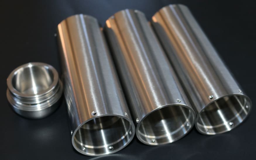
When producing aerospace components for our client, we faced a significant challenge: manufacturing aluminum housings with a wall thickness of just 0.5mm and a height of 40mm (an 80:1 height-to-thickness ratio). Initial production attempts resulted in a 35% rejection rate due to warping and chatter marks. In response, our engineering team implemented a comprehensive optimization approach:
| Initial Process | Optimized Process |
|---|---|
| Standard end mills with 10mm diameter | Necked carbide tools with variable helix |
| Conventional toolpaths with 50% radial engagement | HEM toolpaths with 15% radial engagement |
| Single-sided machining approach | Alternating sides with progressive depth |
| Standard vise fixturing | Custom vacuum fixture with support inserts |
| 35% rejection rate | Less than 3% rejection rate |
The optimized process not only reduced rejection rates but also decreased cycle time by 22% through more efficient material removal strategies. The case demonstrates how integrated application of multiple thin wall machining techniques can transform challenging components from problematic to profitable.
Conclusion
Successful machining of thin walls requires a comprehensive approach that addresses multiple interrelated factors. By understanding the fundamental causes of warping and chatter, manufacturers can implement targeted strategies to overcome these challenges. The key principles include maintaining appropriate cutting forces, managing thermal effects, providing adequate support, and optimizing tool selection and parameters.
At CNCPOR, we bring over 20 years of specialized experience in CNC machining of thin-walled components—including those with extreme height-to-thickness ratios like the aerospace aluminum housings discussed. If you have any questions about thin-wall machining, or need support with your precision component needs, feel free to reach out to our team at any time.