Producing parts with curves, thin walls, deep pockets or intricate shapes present several challenges. Surfaces may vibrate and tools may not reach all areas and costs can increase quickly.
CNC machining addresses these issues through precise control, multi axis movement and dependable accuracy. In this blog post we will explain how manufacturers create complicated parts, which factors influence their cost and how they can be designed for success.
What Are CNC Machined Shaped Parts?
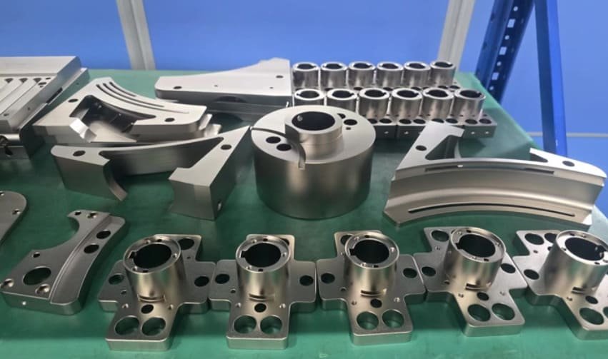
CNC machined shaped parts are components that are produced through a computer controlled subtractive process. The CNC machine removes material from a solid block in a controlled manner. This makes it possible to achieve highly detailed and accurate final shapes.
What Qualifies a Part as a “Shaped” Part
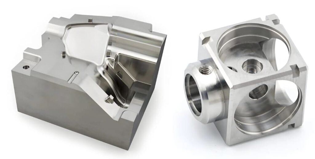
Simple parts normally have prismatic forms and flat surfaces. In contrast, shaped parts include complicated features such as freeform surfaces, pockets as well as undercuts. Such designs need multi axis machining and advanced programming to assure precision.
Key Advantages Compared to Casting, Forging & 3D Printing
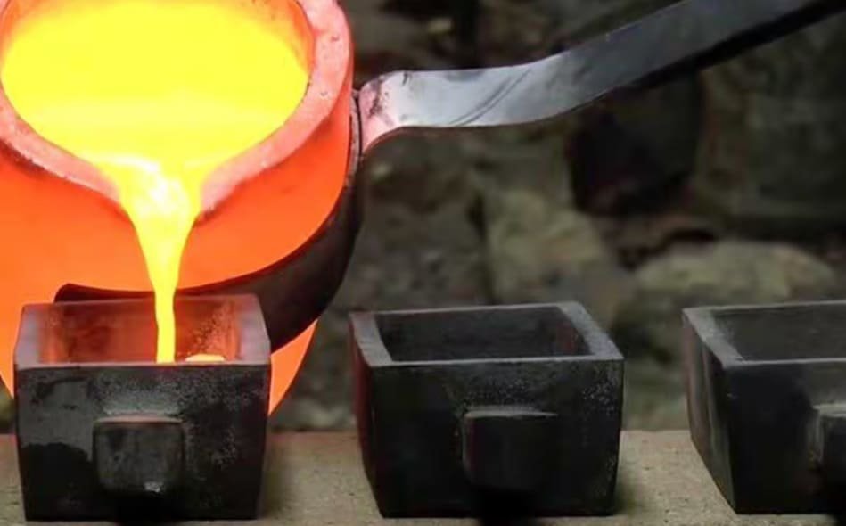
CNC machining achieves very high precision with tolerances reaching up to 0.001″. Therefore it delivers extraordinary surface finishes, often eliminating the need for additional post processing—which is almost always needed in case of 3D printed parts. It also maintains the material’s original strength and avoids internal defects such as porosity which can occur in cast parts.
How CNC Machines Produce Complex Shaped Parts?
CNC machines use a precise, step-by-step process to manufacture parts with complicated shapes. Here is a clear breakdown.
1. Overview of CNC Machining Methods
Different CNC machines shape parts in different ways.
- 3-axis milling produces basic forms.
- 4-axis machines add a rotational axis. This extra movement improves access to contours and reduces the number of setups.
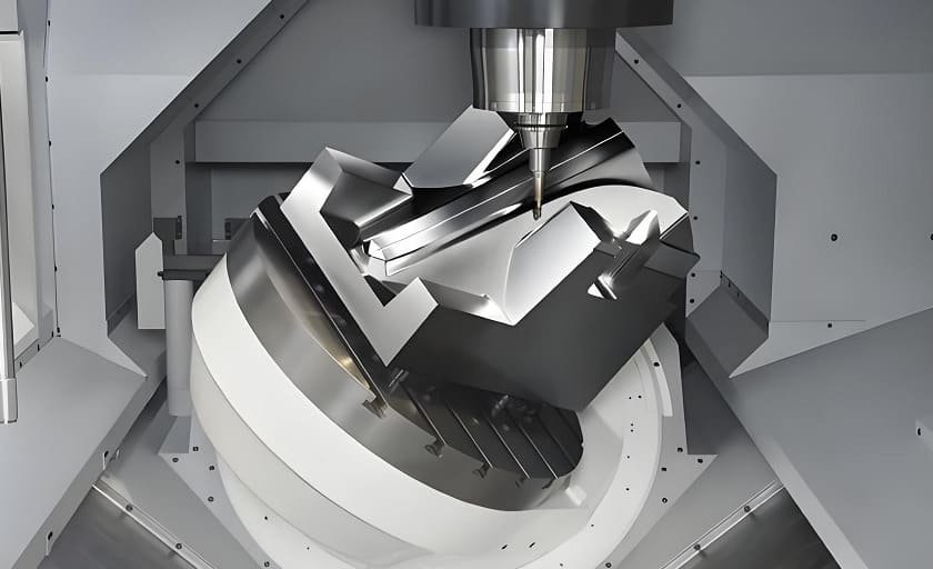
- 5-axis machining lets both the tool and part move simultaneously. This method creates complex curves in a single setup.
- Turning shapes cylindrical features. Mill-turn machines combine milling & turning to produce advanced geometries.
2. From CAD Model to CAM Toolpaths
The process begins with a 3D CAD model which serves as the digital design of the part. After creating the model, it is imported into CAM software. This software generates toolpaths by creating instructions for each step.The software first creates roughing instructions to remove most of the material. It then defines semi-finishing and finishing passes to achieve the final shape and final surface finish.
3. Fixturing, Workholding & Part Orientation
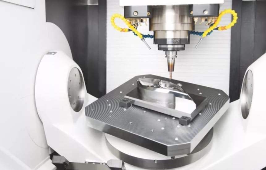
Holding the workpiece securely during machining is essential. Machinists use clamps, vises or custom jigs to position the part for optimal tool access. Some complicated shapes need multiple setups to reach every surface. However 5-axis machines can clamp the part once and reach all sides. This method improves accuracy and reduces the time spent on setups.
4. Cutting Tools & Machining Strategies for Sculpted Surfaces
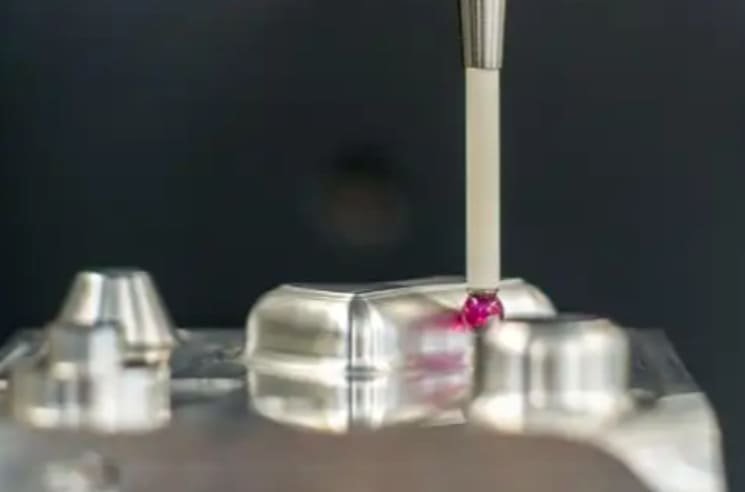
Machining sculpted surfaces needs specialized tools and careful planning. Ball-nose end mills are used to create smooth contours while tapered tools cut angled features. Also there are small diameter tools that can handle fine details. It is also very important to select correct strategies such as adjusting step over and using high speed machining. These choices help achieve the needed finish and accuracy for shaped parts.
Design Fundamentals for Complex Shaped Parts in CNC Machining
A strong design provides the foundation for efficient and affordable CNC machining, especially when dealing with complicated parts.
Design for Manufacturability (DFM) for Shaped Parts
DFM has a critical role when working with complex geometries. It affects both efficiency and cost. By optimizing designs, engineers can achieve better tool access and reduce the number of machine setups. Early planning also helps prevent issues such as tool chatter or part deformation.
At CNCPOR, our engineers can review your CAD files and provide free, practical DFM feedback. This service improves machinability and reduces unnecessary expenses.
Best Practices for Ribs, Bosses & Wall Thicknesses
Wall thickness must be appropriate to keep shaped parts stable. For most metals, the minimum standard is 0.8 mm while plastics need at least 1.5 mm to avoid warping. To increase stiffness, designers can use gussets and ribs. These features reinforce particular areas without increasing the overall mass of the part.
Internal Radii, Fillets & Corner Reliefs
Cutting tools have round profiles which makes sharp internal corners difficult to machine. Therefore it is recommended to include fillets or internal radii. The radius should be at least one-third of the cavity’s depth. If a sharp corner is necessary for assembly, designers can use corner relief. This small recess ensures that the mating part fits correctly.
Managing Slots, Undercuts and Deep Features for Machinability
Undercuts and deep pockets make machining more complicated and more expensive. Therefore it is best to avoid undercuts where possible. If they must be included then keeping them shallow helps the cutting tool reach the area more easily.
Material Selection for Shaped CNC Parts
Choice of the right material has a major role in how a shaped part performs and what it will ultimately cost.
1. Common Metals for Complex Machined Components
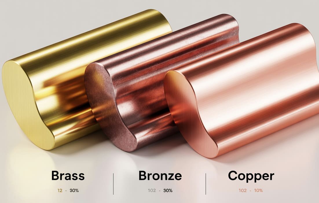
Each metal works best for certain complex parts.
- Aluminum is lightweight, easy to machine and naturally resistant to rust.
- Steels offer strong performance and are affordable, though some types can corrode.
- Stainless steel is both machinable and strong, although it is more expensive.
- Titanium stands out for its high strength-to-weight ratio but it is costly and difficult to machine.
2. Plastics & Composites for Intricate Geometries
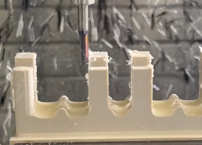
Engineering plastics like Delrin and PEEK are suitable for lightweight and detailed shaped parts. Their low melting points mean that heat must be carefully controlled during machining to avoid melting. Moreover achieving a smooth finish on plastics is often challenging, as tool marks may appear on complicated curves.
At CNCPOR, we offer a wide range of metals and plastics—from aerospace aluminum to engineering PEEK—and can help you choose the best option based on your project budget and requirements.
3. How Material Choice Affects CNC Machining Time & Cost
Material properties influence both machining time and cost. Softer materials like aluminum can be cut quickly and cause less tool wear which ultimately reduces expenses. On the other hand harder materials like titanium need stronger tools and slower machining. This results in longer production times and higher costs.
Tolerances, Surface Finish & Geometric Accuracy
To achieve accuracy in complex parts, it is important to understand how tolerances, surface finish and dimensioning work together.
1. Standard vs Tight Tolerances for Shaped Geometry
Standard machining tolerances are typically around ±0.125 mm which is suitable for most applications. However critical features that need higher precision need tight tolerances—up to ±0.025 mm. Meeting these limits needs additional inspection and more machine time. Therefore they should only be used where truly necessary to keep costs under control.
2. Effective Application of GD&T on Freeform Geometry
Geometric Dimensioning and Tolerancing (GD&T) works exceptionally well for complex freeform surfaces. Instead of marking individual points, it uses profile tolerance to establish a boundary for the surface. This ensures the surface stays within a defined tolerance zone. As a result both design and inspection become easier.
3. Surface Roughness Requirements on Functional Areas
Surface roughness (Ra) impacts both cost and performance. Most general finishes fall between Ra 1.6–3.2 µm. However critical areas such as bearing faces need much smoother finishes, around 0.8 µm Ra or lower. Achieving these finer finishes is more expensive but necessary for correct functionality.
4. Datum Strategies for Freeform & Irregular Features
A clear datum strategy is essential for repeatable inspection of freeform surfaces. Irregular shapes often lack flat planes so datum targets provide stable reference points. The 3-2-1 principle uses three points for the primary plane, two for the secondary and one for the tertiary. This method ensures consistent measurement.
Cost & Lead Time Drivers for Complex Shaped CNC Components
Several factors influence the cost and lead time of complex CNC parts.
- Multiple setups and custom fixtures are needed for complex parts and this in turn increases both cost and lead time.
- Achieving tighter tolerances and smoother finishes on complex parts requires more machine time and inspection which raises expenses.
- Long machining cycles and frequent tool changes are needed for complex geometries. This directly adds to the final price.
- Choosing simpler designs—such as avoiding sharp corners and deep pockets—helps reduce machining time and the overall cost of such parts.
Best Practices for Machining Specific Shaped Features
Machining complex features accurately and avoiding errors requires specific strategies.
Thin Walls, Ribs & Arms
Instead of a deep cut, use multiple shallow passes to prevent chatter on thin features. Machine both sides of the wall alternately to keep stress balanced. If the wall thickness is less than 0.8 mm, leave temporary support ribs. Remove these supports at the end with a finishing pass.
Deep Cavities, Pockets & Channels
Deep pockets make chip removal difficult and increase the risk of tool deflection. Therefore keep the pocket depth to no more than four times the tool diameter to maintain rigidity. Also add stepped pockets and drill corner holes before milling to improve chip evacuation. Additionally use plunge milling to align cutting forces with the Z-axis which increases accuracy and rigidity in deep cavities.
Freeform Surfaces, Sculpted Contours & Organic Shapes
Advanced toolpath planning is essential for machining smooth and organic shapes. Use constant scallop or Z-constant finishing so that the tool step-over stays consistent and the surface remains even. For parts like turbine blades, 5-axis swarf milling works exceptionally well. This technique uses the side of the tool which reduces cycle time and helps achieve a better finish.
Holes and Threads for Shaped Parts
When working on curved surfaces, create a small flat spot first to prevent the drill bit from wandering. Choose the correct pre-drill size to assure threads engage properly. Thread milling provides higher accuracy and a smoother finish, particularly in tough materials.
Quality Control & Inspection of Shaped CNC Parts
Following steps are important for quality control of shaped CNC parts.
- First Article Inspection (FAI) checks the first produced part to assure it meets all design specifications. This step is very important for complex shapes because it helps catch errors before mass production.
- CMMs and probes measure the part’s surface through direct contact This provides highly precise results. On the other hand, 3D scanning captures the entire surface of a complex part quickly for inspection.
- In-process monitoring and toolpath verification detect issues during machining. These checks help maintain consistent accuracy and quality.
At CNCPOR, we use Renishaw and Zeiss CMMs along with 3D optical scanning to inspect every critical surface. This approach lets us achieve the high precision required for detailed and complex parts.
Common Defects in Shaped CNC Parts & How to Prevent Them
- Warping: Parts may bend if internal stress or heat builds up during machining. To prevent this, relieve material stress before machining and control heat throughout the process.
- Chatter Marks: Vibration patterns appear on the surface when the setup isn’t rigid. Avoid these marks by using sharp tools and adjusting machine speeds.
- Mismatched Blends: Imperfections may appear where toolpaths meet if the machine or programming isn’t accurate. Proper machine calibration resolves this issue.
- Tool Witness Lines: Cutting tool paths may leave visible lines. Changing the tool angle and path can reduce or eliminate these lines.
Examples of Shaped CNC Parts in Industries
CNC machining can produce many types of complex shaped parts for advanced industries. Here are a few examples
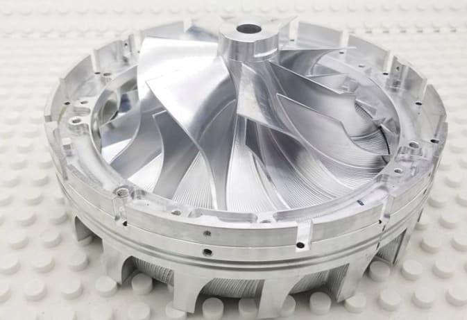
Turbine & Impeller Blades
Jet engines and power plants depend on blades with complex and twisted surfaces. 5-axis CNC machines shape these blades from tough metals with high precision. This accuracy improves both engine efficiency and performance.
Medical Implants
CNC technology makes it possible to produce custom medical parts such as hip and knee implants. Surgeons can choose body-safe materials like titanium for these implants. This process ensures that each implant fits the patient perfectly and remains durable.
Injection Molds
Injection molds contain intricate cavities, core and other complex features such as cooling channels. High speed milling is usually used to create these complex features with very tight tolerances.
Complex Brackets
Automotive and aerospace industries demand brackets with deep pockets and unique angles. Precision CNC machining produces these custom parts in small batches from strong aluminum. This process ensures every bracket meets exact requirements.
Housings & Enclosures
Optical scopes and electronics need protective housings with tight tolerances. CNC milling achieves tolerances as tight as ±0.01 mm for these cases. This keeps internal components protected and properly aligned.
Optical & Fluidic Components
Devices in fluidics and optics need parts with high surface quality and precision. CNC machines produce items like fluid manifolds and lens holders with micron-level accuracy. This ensures precise control of light and fluids.
How to Choose a CNC Partner for Shaped Parts
Choice of the right manufacturing partner is essential to meet the requirements of shaped parts.
1. Evaluation of Technical Capabilities
A strong partner provides the right equipment and expertise for your project. When evaluating suppliers, consider the following
- Advanced Equipment: The supplier should use up-to-date multi axis CNC machines capable of producing complex shapes.
- Strong Quality Control: Ensure they have in-house inspection tools such as CMMs to maintain precision.
- Skilled Team: Their engineers should have experience with CAD/ CAM software and various materials.
2. Important Questions to Ask
Direct questions help you understand a supplier’s focus on quality and teamwork.
- “What quality certifications do you have?” Reliable partners typically hold certifications such as ISO 9001.
- “What inspection equipment do you use?” They should rely on calibrated tools, including CMMs.
- “How do you handle design feedback?” A capable supplier reviews your design for manufacturability (DfM) and offers suggestions.
3. What to Include in Your RFQ
A complete Request for Quotation (RFQ) helps you receive accurate quotes. Always include:
- 3D CAD models such as .STEP files.
- 2D drawings with all critical dimensions, tolerances and surface finish requirements.
- Details about material, order quantities and the required inspection level.
How to Build a Long Term Relationship with Your Machining Supplier
To build a long lasting relationship with your machining supplier, start with clear and timely communication. Begin discussing DFM before finalizing the design so issues can be identified early and costs can be reduced. Use a reliable revision control system to assure both teams are working on the latest designs and to prevent errors. Plus establish a clear feedback process so problems can be resolved and improvements can be suggested.
Case Studies of CNC Machined Shaped Parts at CNCPOR
Aerospace Impeller Component
An aerospace client demanded an impeller with extremely thin and complex blades. Manufacturing the freeform surfaces was a major challenge. Therefore we relied on our advanced 5-axis CNC machines to mill the part with high precision. This approach helped us achieve the required geometry while maintaining structural strength.
Medical Implant with Complex Contours
A medical device partner needed a titanium spinal implant with intricate contours so it could fit the patient’s anatomy accurately. We used our advanced 5-axis CNC grinding to produce this part. This process delivered a surface finish of Ra 0.05 μm and tolerances of ±0.001 mm. These specifications were important for the implant’s biocompatibility and performance.
Automotive Bracket with Optimized Topology
A motorsport team requested a lightweight bracket designed using topology optimization. The main challenge in this case was machining the organic, skeletal shape while maintaining strength. But our multi-axis CNC machining process successfully handled this complexity. The final part was extremely light yet still met all strength requirements.
To Sum Up
CNC machining is a dependable method to produce shaped parts with high accuracy and quality. A solid understanding of design, material selection and machining steps helps you create parts that are easy to manufacture and meet your goals.
If you need expert CNC Machining service for complex components then CNCPOR is your best option. You can contact us anytime.
Related Questions
Is CNC machining a good alternative to 3D printing for complex shapes?
3D printing works best for detailed internal structures. However CNC machining is more suitable when you need complex parts with tight tolerances and smooth surfaces.
What steps help reduce the cost of a complex CNC part?
You can reduce costs by simplifying the design, choosing affordable materials and using tight tolerances only where necessary. Splitting a complex part into several simpler pieces can also be helpful.
What files should I send to get an accurate CNC machining quote?
To get a precise quote, send a 3D CAD file—such as IGES, STEP or STL—along with a 2D drawing that includes the material and needed tolerances.
How long does it take to produce a complex CNC prototype?
A complex CNC prototype can take anywhere from a few days to several weeks. This timeline depends on the part’s design, material selection and any required finishing steps.