Pogo pins represent a critical component in modern electronics, providing reliable electrical connections in countless applications. When manufactured through CNC machining processes, these spring-loaded connectors achieve exceptional precision and performance characteristics that surpass conventional production methods.
From material selection to quality control procedures, we’ll examine how CNC machining enhances the production of these essential components while meeting rigorous industry standards. Whether you’re developing consumer electronics, medical devices, or automotive testing equipment, understanding the technical nuances of CNC-machined pogo pins can significantly impact your product’s reliability and performance.
What Are Pogo Pins and Their Role in Electrical Connectivity
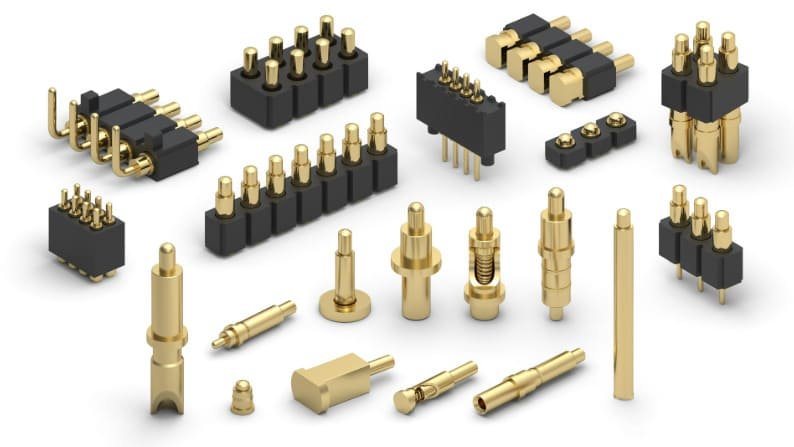
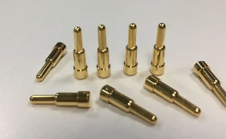
Pogo pins, also known as spring-loaded contacts or spring probes, are specialized electrical connectors designed to establish reliable temporary or semi-permanent connections between electronic components. Their name derives from their resemblance to pogo sticks, as they utilize an internal spring mechanism that allows for vertical compression while maintaining consistent contact pressure.
The basic structure of a pogo pin consists of three primary components:
- Plunger: The moving contact point that extends from the barrel and makes direct electrical contact with the target surface
- Spring: The internal compression mechanism that provides consistent contact force and compensates for height variations and misalignments
- Barrel: The outer housing that contains the spring and guides the plunger movement
These components work together to create a self-adjusting electrical connection that maintains reliable contact even when subjected to vibration, thermal expansion, or slight misalignments. This adaptive quality makes pogo pins invaluable in applications where consistent electrical performance is critical.
In accordance with IEC 60512 standards for electrical connector testing, pogo pins typically maintain contact resistance below 30 mΩ throughout their operational lifespan, with premium CNC-machined variants achieving even lower resistance values of 10-15 mΩ.
How CNC Machining Enhances Precision in Pogo Pin Manufacturing
Unlike traditional manufacturing methods such as stamping or manual turning, CNC machining offers computer-controlled accuracy that consistently achieves tolerances as tight as ±0.005mm.
Key Advantages of CNC Machining for Pogo Pin Production
Dimensional Precision
CNC machines follow programmed toolpaths with exceptional accuracy, producing pogo pin components with consistent dimensions batch after batch. This precision is crucial for maintaining reliable spring compression characteristics and ensuring proper fit within assembly housings.
Material Optimization
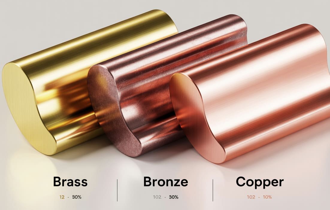
CNC machining allows for the efficient use of high-performance materials like beryllium copper and phosphor bronze, maximizing the electrical and mechanical properties of each pogo pin component while minimizing material waste.
Surface Finish Quality
The controlled cutting parameters of CNC machining create superior surface finishes on pogo pin barrels and plungers. This reduces friction during operation and enhances electrical conductivity at contact points, resulting in lower contact resistance and improved signal integrity.
Complex Geometries
Advanced multi-axis CNC machines can produce intricate features on pogo pin components, including specialized tip geometries, internal threading, and precise spring chambers that would be difficult or impossible to achieve with conventional manufacturing methods.
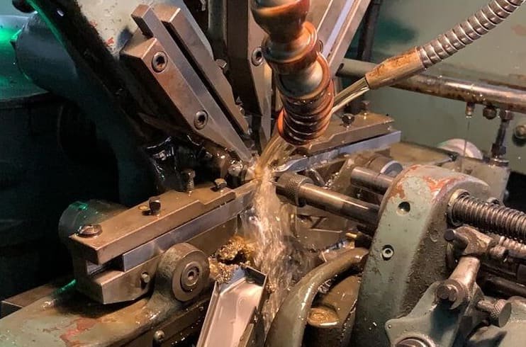
The Process of CNC Machining Pogo Pins
- CAD modeling of pogo pin components with precise dimensional specifications
- CAM programming to generate optimized toolpaths for each component
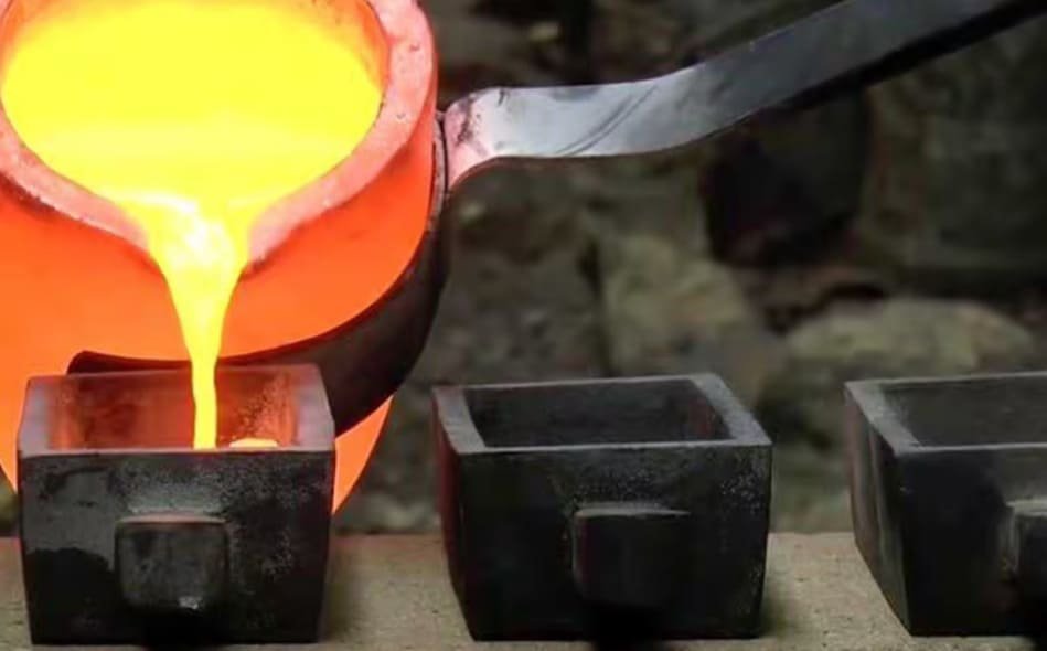
- Material selection and preparation of raw stock (typically brass, copper alloys, or stainless steel)
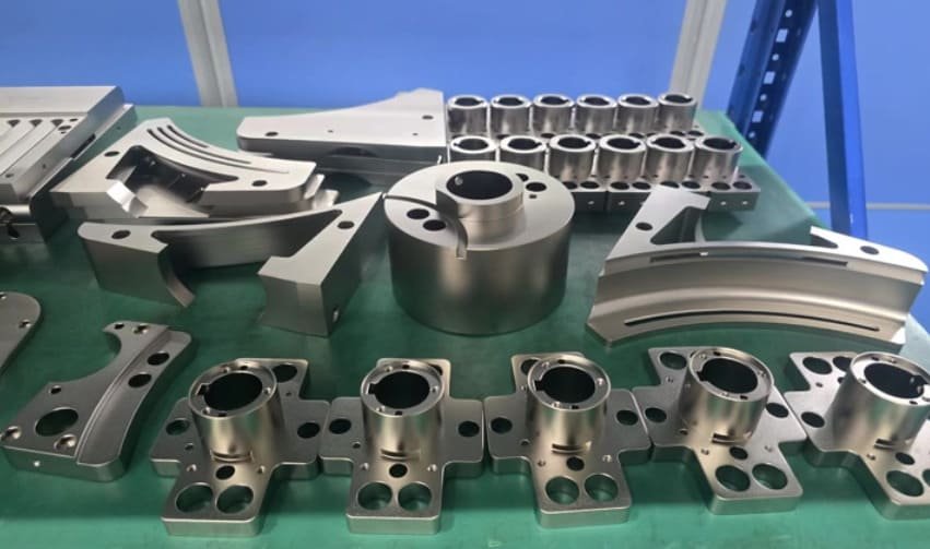
- CNC turning operations to create the basic cylindrical forms
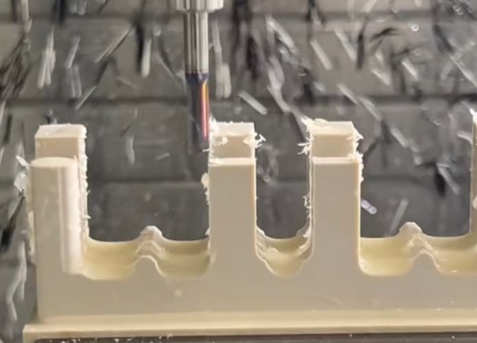
- CNC milling for any specialized features or geometries
- Precision drilling for internal spring chambers
- Surface finishing operations for improved conductivity and wear resistance
- Quality inspection using precision measurement equipment
Common Applications of CNC-Machined Pogo Pins
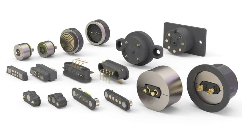
The exceptional reliability and customization potential of CNC-machined pogo pins make them ideal for a wide range of industries and applications where consistent electrical connectivity is critical. Here are some of the most common implementations:
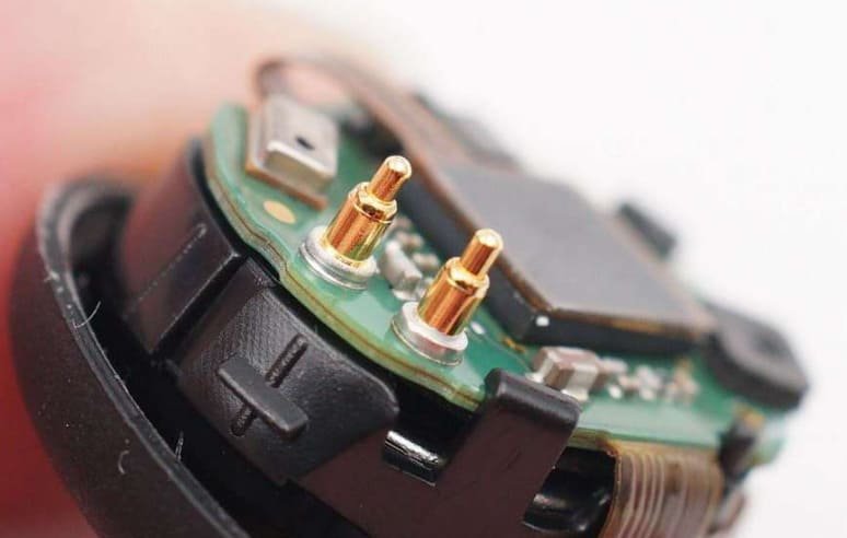
Consumer Electronics
- Charging interfaces for smartphones, tablets, and wearables
- Battery connections in portable devices
- Docking stations and peripheral connections
- Camera module interfaces in slim devices
Technical Specifications: Typically utilizing gold-plated brass pins with 0.5-1.5mm diameter, 2-4mm working travel, and rated for 10,000+ mating cycles.
Medical Devices
- Patient monitoring equipment connections
- Disposable sensor interfaces
- Medical imaging system connectors
- Implantable device testing
Technical Specifications: Often utilizing biocompatible stainless steel or gold-plated components, 0.3-1.0mm diameter, with stringent cleanliness requirements per ISO 13485 standards.
Automotive Testing
- ECU and PCB functional testing
- In-vehicle diagnostics connections
- Battery management system interfaces
- Sensor calibration equipment
Technical Specifications: Typically high-current capacity pins (3-5A per pin), with robust construction for harsh environments, compliant with automotive testing standards like ISO 16750.
Aerospace and Defense
CNC-machined pogo pins find critical applications in aerospace systems where reliability under extreme conditions is paramount. These include avionics testing interfaces, satellite deployment mechanisms, and mission-critical communication systems. Per MIL-STD-1344 requirements, these pins must maintain functionality through severe vibration, thermal cycling, and vacuum conditions.
Industrial Automation
In factory automation, CNC-machined pogo pins serve as quick-connect interfaces for interchangeable tooling, robotic end effectors, and modular production equipment. Their ability to withstand hundreds of thousands of mating cycles makes them ideal for high-volume manufacturing environments where equipment reconfiguration is frequent.
Advantages of CNC-Machined Pogo Pins Over Stamped Alternatives
While stamped pogo pins offer cost advantages in extremely high-volume production scenarios, CNC-machined alternatives provide superior performance characteristics that justify their implementation in applications where reliability, precision, and consistent electrical performance are critical requirements.
Advantages of CNC-Machined Pogo Pins
- Superior Dimensional Accuracy: CNC machining achieves tolerances of ±0.005mm compared to ±0.025mm for stamped alternatives
- Better Surface Finish: Ra values as low as 0.2μm versus 0.8-1.6μm for stamped components
- Enhanced Durability: Homogeneous material structure without the stress concentrations created during stamping
- Lower Contact Resistance: Typically 10-15mΩ versus 20-30mΩ for stamped alternatives
- Greater Design Flexibility: Ability to create complex geometries and specialized tip configurations
- Consistent Spring Characteristics: More precise control of spring chamber dimensions for predictable compression force
Limitations of Stamped Pogo Pins
- Limited Geometric Complexity: Restricted to designs that can be formed through stamping processes
- Material Deformation: Stamping creates internal stresses that can affect long-term performance
- Inconsistent Spring Tension: Greater variation in spring characteristics between production batches
- Higher Contact Resistance: Rougher surface finish leads to increased electrical resistance
- Reduced Lifespan: Typically rated for fewer mating cycles than CNC-machined alternatives
- Less Precise Alignment: Greater dimensional variation can cause alignment issues in high-density applications
Design Considerations for Spring-Loaded Contact Systems
Engineers must balance electrical performance, mechanical durability, and manufacturing feasibility when specifying CNC-machined pogo pins.
Critical Design Parameters
| Parameter | Description | Typical Range | Design Considerations |
|---|---|---|---|
| Working Stroke | Maximum travel distance of the plunger | 0.3mm – 5.0mm | Must accommodate tolerance stack-up and misalignment while preventing over-compression |
| Spring Force | Contact pressure exerted by the spring | 20g – 300g | Higher forces improve electrical contact but increase wear and mechanical stress |
| Current Rating | Maximum current capacity | 1A – 10A | Determined by pin diameter, material, and plating thickness |
| Tip Geometry | Shape of the contact surface | Crown, flat, pointed, concave | Must match target surface characteristics for optimal contact |
| Pitch Spacing | Distance between adjacent pins | 0.5mm – 3.0mm | Affects connector density and isolation between contacts |
Design Optimization Strategies
Tip Geometry Selection
Choose appropriate tip shapes based on the target surface. Crown tips work well for flat surfaces, while pointed tips are better for penetrating oxides or contaminants.
Spring Rate Calculation
Determine optimal spring characteristics using Hooke’s Law (F = kx) to achieve consistent contact force throughout the working stroke.
Alignment Features
Incorporate guide features in housing designs to ensure proper pin alignment and prevent lateral forces that could damage the pins.
Environmental Protection
Consider sealing requirements for applications exposed to moisture, dust, or corrosive environments.
Signal Integrity
For high-frequency applications, minimize pin length and optimize barrel design to reduce inductance and maintain signal integrity.
According to IEC 60512-5-2 standards, properly designed spring-loaded contact systems should maintain consistent contact resistance through a minimum of 10,000 actuation cycles, with premium CNC-machined systems often exceeding 100,000 cycles in controlled environments.
Material Selection Tips for CNC-Machined Pogo Pins
Different applications require specific material properties to meet electrical, mechanical, and environmental requirements.
Common Base Materials for Pogo Pin Components
| Material | Electrical Conductivity | Tensile Strength | Spring Properties | Corrosion Resistance | Ideal Applications | Limitations |
|---|---|---|---|---|---|---|
| Beryllium Copper (BeCu) | 22-28% IACS | 1300-1400 MPa (heat treated) | Excellent elasticity and fatigue resistance | Good | High-performance connectors requiring exceptional spring characteristics and reliability | Higher cost, requires careful handling during manufacturing due to beryllium content |
| Phosphor Bronze | 15-20% IACS | 700-850 MPa | Good elasticity and fatigue resistance | Excellent | Cost-effective alternative to BeCu for applications with moderate spring requirements | Lower conductivity than BeCu, slightly reduced spring performance |
| Brass | 28-33% IACS | 300-550 MPa | Moderate, suitable for limited cycling applications | Moderate, improves with plating | Cost-sensitive applications with moderate performance requirements | Limited spring properties, potential for stress relaxation over time |
Plating Materials and Their Properties
Gold (Au) Plating
Gold plating provides excellent conductivity (71% IACS) and superior corrosion resistance. Typically applied in thicknesses of 0.1-2.0μm, it’s ideal for low-contact-resistance applications. Hard gold (gold with cobalt or nickel) offers improved wear resistance for high-cycle applications, though at a higher cost than other plating options.
Nickel (Ni) Plating
Nickel plating offers good hardness (400-500 HV) and wear resistance at a lower cost than gold. With moderate conductivity (20-25% IACS), it’s often used as an underplate beneath gold to reduce costs while maintaining performance. It provides excellent corrosion protection but may develop increased contact resistance over time.
When selecting materials for CNC-machined pogo pins, engineers must consider the entire operating environment, including temperature range, humidity, potential exposure to corrosive substances, and expected service life. For applications requiring compliance with MIL-STD-1344 or IEC 60512 standards, material selection must be documented as part of the qualification process.
Quality Control Methods for Machined Contact Components
Ensuring consistent quality in CNC-machined pogo pins requires comprehensive inspection protocols and testing procedures.
Dimensional Inspection Techniques
- Optical Measurement Systems: Non-contact measurement using high-resolution cameras and software to verify critical dimensions with accuracy up to ±0.001mm
- Coordinate Measuring Machines (CMM): Precision probing systems that create detailed dimensional reports for complex geometries
- Profile Projectors: Shadow-based measurement systems for verifying outline profiles against master templates
- Thread Gauges: Specialized tools for verifying internal and external thread specifications on threaded pogo pin components
Electrical Performance Testing
In accordance with IEC 60512-2-1 standards, electrical testing of pogo pins typically includes:
- Contact Resistance Measurement: Using four-wire Kelvin method to accurately measure resistance below 30mΩ
- Current Capacity Verification: Testing pins at rated current while monitoring temperature rise
- Insulation Resistance: Verifying electrical isolation between adjacent pins in multi-pin assemblies
- High-Potential (Hi-Pot) Testing: Applying voltage between pins to verify dielectric strength
Mechanical Testing Procedures
Spring Force Testing
Using calibrated force gauges to measure the compression force at various stroke positions. This verifies that spring characteristics meet design specifications and remain consistent across production batches. Typical testing involves measuring force at 25%, 50%, 75%, and 100% of rated stroke.
Durability Cycling
Automated test equipment compresses and releases pins through thousands of cycles to verify mechanical durability. Contact resistance is measured periodically throughout the test to ensure electrical performance remains stable. Premium CNC-machined pogo pins should maintain consistent performance through at least 100,000 cycles.
Surface Finish and Plating Inspection
- X-Ray Fluorescence (XRF): Non-destructive measurement of plating thickness with accuracy to ±0.1μm
- Surface Roughness Testing: Profilometer measurement of Ra values to verify surface finish quality
- Salt Spray Testing: Accelerated corrosion testing per ASTM B117 to verify plating integrity
- Adhesion Testing: Verifying plating adhesion through tape tests or more rigorous methods
Implementing comprehensive quality control procedures throughout the manufacturing process ensures that CNC-machined pogo pins consistently meet performance specifications and reliability requirements. Documentation of these quality processes is often required for components used in medical, aerospace, or automotive applications.
Real-World Applications: CNC Machining Pogo Pins in Action
Case Study 1: High-Density Test Fixture for Automotive ECU Testing
A automotive electronics manufacturer required a test fixture capable of simultaneously contacting 1,200+ test points on engine control units (ECUs). The solution involved custom CNC-machined pogo pins with the following specifications:
- Pin Diameter: 0.68mm to accommodate 0.8mm pitch requirements
- Material: Beryllium copper with 1.5μm hard gold plating
- Spring Force: 80g at mid-stroke to ensure reliable contact with varying pad heights
- Current Rating: 3A continuous for power testing capabilities
- Durability: Rated for 500,000 test cycles to meet production volume requirements
The implementation of precision CNC-machined pogo pins reduced test failures by 64% compared to the previous test system, resulting in significant production yield improvements and cost savings.
Case Study 2: Medical Wearable Device Charging Interface
A medical device manufacturer developing a continuous glucose monitoring system needed a reliable charging interface that could withstand daily use while maintaining biocompatibility. The solution utilized custom CNC-machined pogo pins with these specifications:
- Pin Diameter: 0.5mm for compact device integration
- Material: Stainless steel 316L with 0.5μm gold plating
- Spring Force: 25g to allow easy connection while ensuring reliable contact
- Sealing: IP67-rated housing design to prevent moisture ingress
- Biocompatibility: Materials compliant with ISO 10993 standards
The CNC-machined pogo pin solution provided a 99.8% connection reliability rate over the device’s three-year expected lifespan, significantly outperforming alternative connector technologies considered during development.
Case Study 3: Aerospace Vibration Test Equipment
A manufacturer of satellite components required a specialized test system capable of maintaining electrical connections during vibration testing. The solution incorporated custom CNC-machined pogo pins with these characteristics:
- Pin Diameter: 1.2mm for enhanced mechanical stability
- Material: Phosphor bronze with nickel underplate and gold surface plating
- Spring Force: 150g to maintain contact during high-vibration conditions
- Temperature Range: -55°C to +125°C operational capability
- Signal Integrity: Controlled impedance design for high-frequency testing
The implementation enabled reliable testing under extreme vibration conditions (up to 20G RMS), allowing for comprehensive qualification testing without the signal dropouts experienced with previous connector technologies.
Cost-Benefit Analysis for High-Volume Production
When considering CNC machining for pogo pin production, we must carefully evaluate the economic factors that influence total cost of ownership. While CNC machining typically involves higher per-unit production costs compared to stamping, the performance benefits and reduced failure rates often justify the investment for many applications.
Production Volume Considerations
| Production Volume | Recommended Manufacturing Approach | Cost Factors | Quality Considerations |
|---|---|---|---|
| Low Volume (1-5,000 units) | Full CNC machining | Higher per-unit cost, low tooling investment | Highest precision and consistency |
| Medium Volume (5,000-50,000 units) | Hybrid approach: CNC for critical components, stamping for simple parts | Balanced tooling and per-unit costs | Good precision for critical features |
| High Volume (50,000+ units) | Stamping with CNC secondary operations | Higher tooling investment, lower per-unit cost | Acceptable precision with proper quality control |
Total Cost of Ownership Analysis
When evaluating manufacturing methods for pogo pins, consider these factors that influence total cost of ownership:
Direct Manufacturing Costs
- Material costs: Premium materials for CNC machining vs. standard materials for stamping
- Machining time: CNC production rates vs. high-speed stamping throughput
- Tooling investment: Minimal for CNC vs. substantial for high-volume stamping
- Setup and changeover costs: More flexible with CNC for varied production runs
Indirect Cost Factors
- Quality control costs: Typically lower for CNC due to higher consistency
- Failure rate in field: Lower warranty and replacement costs with CNC-machined pins
- Design flexibility: Easier and less costly design iterations with CNC manufacturing
- Inventory carrying costs: Lower minimum order quantities with CNC production
According to industry data, while CNC-machined pogo pins may cost 30-50% more per unit than stamped alternatives, the total cost of ownership can be lower for applications where reliability is critical. Field failure rates for CNC-machined pins are typically 3-5 times lower than stamped alternatives, resulting in significant savings in warranty claims, field service, and customer satisfaction.
Conclusion
CNC machining has revolutionized the production of pogo pins, enabling unprecedented levels of precision, reliability, and customization for critical electrical connectivity applications. By leveraging the advantages of computer-controlled manufacturing processes, engineers can develop spring-loaded contact solutions that outperform conventional alternatives in terms of durability, electrical performance, and dimensional accuracy.
When implementing CNC-machined pogo pins in your designs, careful consideration of material selection, design parameters, and quality control procedures will ensure optimal performance for your specific application requirements. While the initial manufacturing costs may be higher than alternative production methods, the enhanced reliability and reduced failure rates often result in a lower total cost of ownership for applications where consistent electrical connectivity is critical.