In the precision world of machining, burrs are like uninvited guests that show up at the edges of your workpiece. These unwanted material projections not only affect the aesthetic appeal of machined parts but can also compromise functionality, assembly fit, and even safety. This comprehensive guide will walk you through everything you need to know about burrs in machining and how to deal with them effectively.
What Is a Burr in Machining?
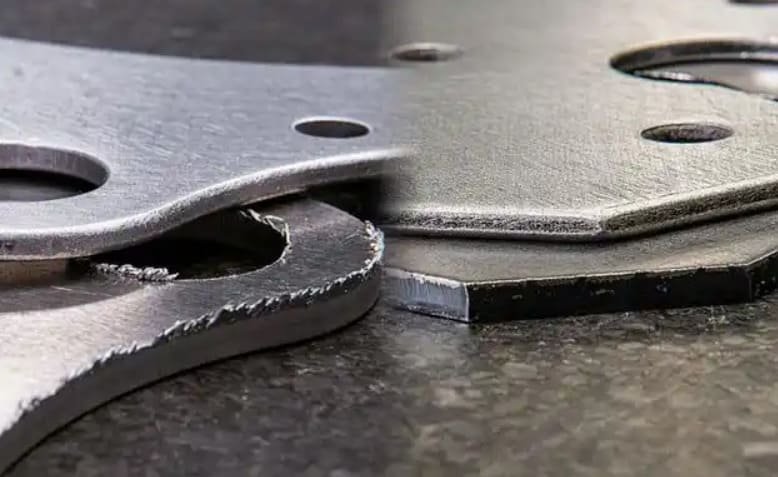
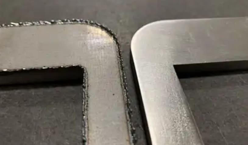
A burr in machining is a small, unwanted projection of material that forms on the edges of a workpiece during various manufacturing processes. Think of burrs as the metal equivalent of paper cuts – small but potentially problematic. When a cutting tool interacts with the workpiece material, it doesn’t always create a perfectly clean separation. Instead, it can push or deform material, creating these unwanted projections.
To visualize this, imagine cutting bread with a dull knife. Rather than making a clean slice, the knife pushes some of the bread to the side, creating jagged edges. Similarly, in machining, when tools aren’t sharp enough or cutting conditions aren’t optimal, material gets pushed rather than cleanly cut, forming burrs.
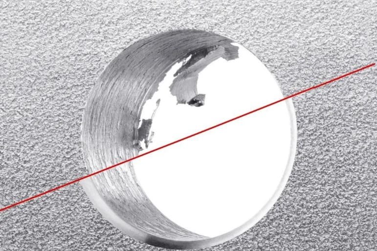
Burrs can range from microscopic projections visible only under magnification to substantial formations that can be felt by hand. They typically appear along edges, in drilled holes, at the intersection of surfaces, and at the exit points of cutting tools.
5 Common Types of Burrs in Machining
Here are the five most common types you’ll encounter in machining operations:
1. Rollover Burrs
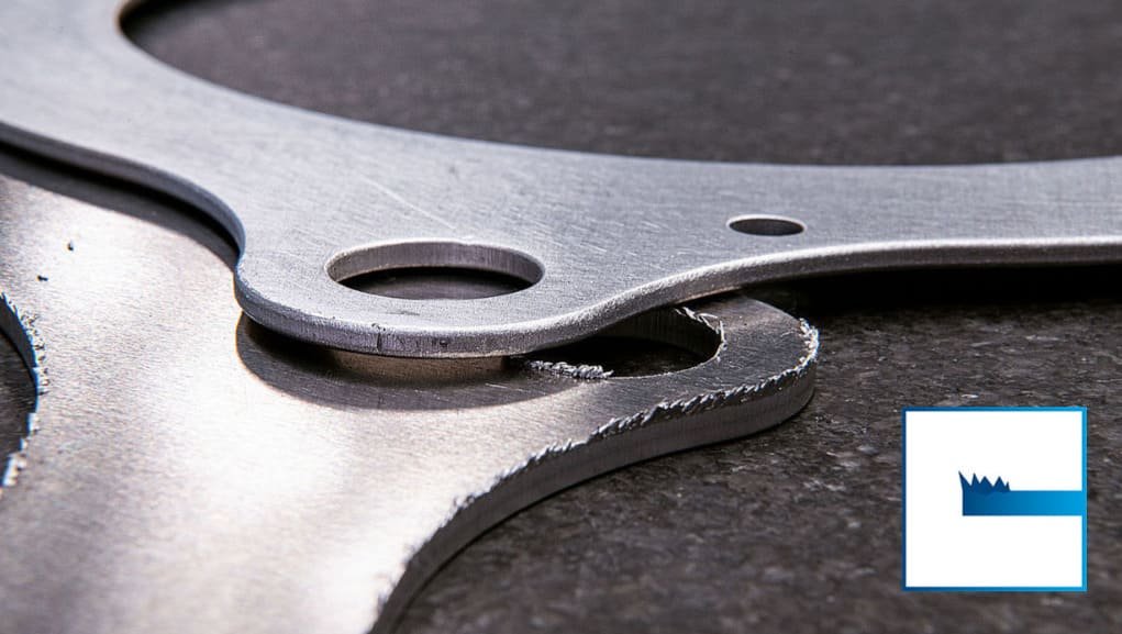
Rollover burrs (also called exit burrs) are the most common type in machining. They form when the cutting tool pushes material over an edge instead of cleanly shearing it. Visually, they appear as a curved projection that “rolls over” the edge of the workpiece. These burrs typically form on the exit side of the cut where the tool leaves the workpiece. The size of rollover burrs directly correlates with the depth of cut – deeper cuts generally produce larger burrs.
2. Poisson Burrs
Poisson burrs form on the entrance side of a machining operation. When the tool first contacts the material, it creates a lateral material flow due to the Poisson effect (hence the name). These burrs appear as small projections perpendicular to the cutting direction. They’re typically smaller than rollover burrs and form when material is pushed away from the edge rather than being cleanly cut.
3. Tear Burrs
Tear burrs result when material is torn away rather than cut cleanly. They have a jagged, irregular appearance and are common in punching operations or when machining ductile materials with dull tools. These burrs are characterized by their rough, uneven texture and unpredictable shape, making them particularly challenging to remove consistently.
4. Breakout Burrs
Also known as cut-off or breakoff burrs, these form when a piece breaks away from the workpiece rather than being cut cleanly. They’re common in sawing operations, automatic screw machines, and when separating parts from stock. Breakout burrs have a fractured appearance and are often accompanied by material deformation around the breakage point.
5. Thermal Burrs
Thermal burrs form during heat-intensive processes like laser cutting, plasma cutting, or welding. These burrs are actually melted and re-solidified material that adheres to the edges of the workpiece. They often appear as hardened droplets or slag and can be particularly difficult to remove due to their different material properties compared to the base material.
| Burr Type | Formation Location | Visual Characteristics | Common Processes |
|---|---|---|---|
| Rollover | Exit side of cut | Curved projection following tool direction | Milling, drilling, turning |
| Poisson | Entrance side of cut | Small, perpendicular projection | Face milling, drilling |
| Tear | Along cut edges | Jagged, irregular projection | Punching, shearing |
| Breakout | At material separation points | Fractured appearance | Sawing, parting operations |
| Thermal | Along heat-affected zones | Hardened droplets or slag | Laser cutting, plasma cutting, welding |
7 Primary Causes of Burr Formation
Understanding what causes burrs is the first step toward preventing them. Here are the seven primary factors that contribute to burr formation in machining operations:
1. Tool Wear and Condition
Dull or worn cutting tools are one of the leading causes of burr formation. When a tool loses its sharp edge, it tends to push material rather than cut it cleanly. Regular tool inspection and replacement are essential for minimizing burrs. For example, a worn end mill used in aluminum machining might produce significant rollover burrs even with optimal cutting parameters.
2. Feed Rate and Cutting Speed
Improper feed rates and cutting speeds can significantly impact burr formation. Too high a feed rate can cause material tearing, while too slow a feed rate can lead to excessive heat generation and thermal burrs. Finding the optimal balance for each material and operation is crucial. For instance, when milling stainless steel, a feed rate that’s too aggressive will typically produce larger exit burrs.
3. Material Properties
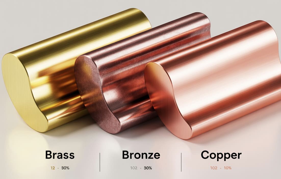
The properties of the workpiece material greatly influence burr formation. Ductile materials like aluminum and mild steel tend to form larger burrs than brittle materials like cast iron. Material hardness, grain structure, and thermal properties all play roles in how burrs form. For example, free-machining brass typically produces smaller burrs than standard brass alloys due to its improved machinability.
4. Tool Geometry and Design
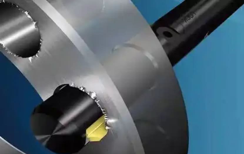
The geometry of cutting tools significantly affects burr formation. Factors like rake angle, clearance angle, and cutting edge radius all influence how material is removed. Tools designed with positive rake angles typically produce smaller burrs than those with negative rake angles. For drilling operations, specialized drill point geometries can dramatically reduce exit burrs.
5. Cutting Direction and Strategy
The direction of cut relative to the workpiece edge can determine the size and type of burrs formed. In milling operations, climb milling (where the cutter rotation matches the feed direction) often produces smaller burrs than conventional milling. Similarly, the approach angle when a tool enters or exits a workpiece can be optimized to minimize burr formation.
6. Workpiece Support and Clamping
Inadequate workpiece support or clamping can lead to vibration and deflection during machining, resulting in inconsistent cuts and increased burr formation. Ensuring rigid fixturing is particularly important when machining thin-walled components or when making interrupted cuts. For example, proper edge support when drilling through thin sheet metal can virtually eliminate breakout burrs.
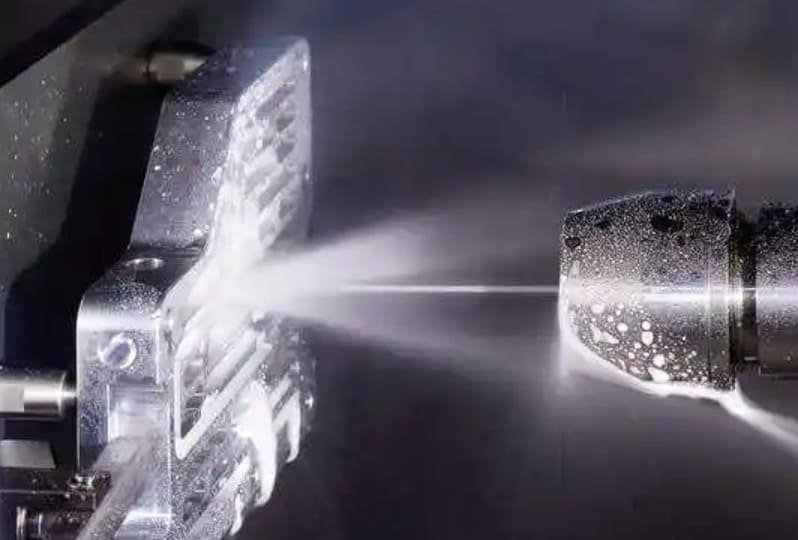
7. Thermal Effects
Excessive heat generation during machining can lead to material softening and increased plastic deformation, resulting in larger burrs. Proper cooling and lubrication strategies can help manage thermal effects. When machining titanium alloys, for instance, insufficient cooling can lead to significant thermal burrs due to the material’s poor thermal conductivity.
6 Effective Burr Removal Methods Compared
Once burrs have formed, they need to be removed to ensure part quality and functionality. Here’s a comparison of six common deburring methods, each with its own advantages and limitations:
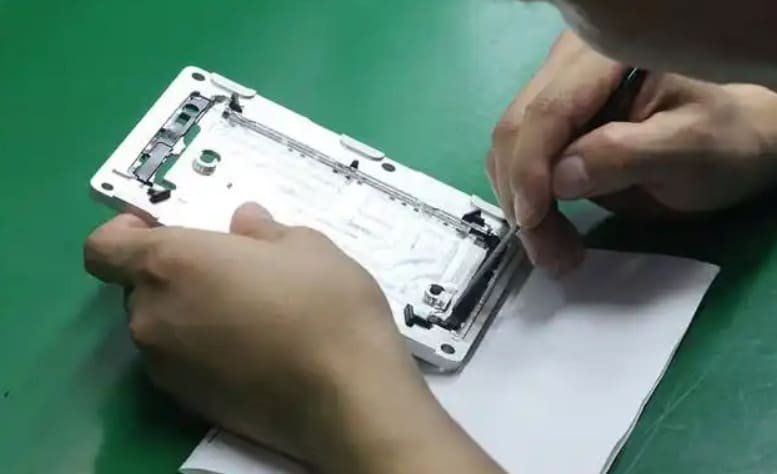
1. Manual Deburring
Manual deburring involves using hand tools like files, scrapers, deburring knives, and sandpaper to physically remove burrs. While labor-intensive, it offers precise control for complex geometries and delicate features. This method is ideal for low-volume production, prototype parts, or areas that automated methods can’t reach.
Pros:
- No specialized equipment required
- Effective for complex geometries
- Selective application possible
- Low initial investment
Cons:
- Labor-intensive and time-consuming
- Results depend on operator skill
- Inconsistent results between parts
- Not cost-effective for high volumes
2. Mechanical Deburring
Mechanical deburring encompasses methods like brushing, grinding, and tumbling. These techniques use abrasive media to remove burrs through mechanical action. Brushing with wire or abrasive brushes is effective for accessible edges, while tumbling involves placing parts in a container with abrasive media that removes burrs as the container rotates or vibrates.
Pros:
- Higher throughput than manual methods
- Consistent results across batches
- Can improve surface finish simultaneously
- Adaptable to various part sizes
Cons:
- May not reach internal features
- Risk of dimensional changes
- Can round sharp edges
- May require specialized equipment
3. Thermal Deburring
Thermal deburring (TEM – Thermal Energy Method) places parts in a sealed chamber filled with a combustible gas mixture. When ignited, the rapid combustion creates temperatures up to 3000°C that vaporize thin burrs while leaving the bulk material unaffected due to its greater mass and thermal capacity.
Pros:
- Removes burrs from all surfaces simultaneously
- Effective for internal and cross-hole burrs
- Consistent results regardless of part complexity
- High throughput for batch processing
Cons:
- High equipment cost
- Not suitable for heat-sensitive materials
- May require secondary cleaning
- Limited to burrs with high surface-to-volume ratio
4. Electrochemical Deburring
Electrochemical deburring (ECD) uses electrolysis to dissolve burrs. The part is placed in an electrolyte solution with a cathode positioned near the burr. When current flows, the burr dissolves without affecting the main part. This method is particularly effective for internal features and cross-holes that are difficult to access with other methods.
Pros:
- Excellent for internal and cross-hole burrs
- No mechanical or thermal stress on parts
- Highly precise and controllable
- No effect on material properties
Cons:
- Requires conductive materials
- Complex setup and tooling
- Higher cost per part
- Chemical handling considerations
5. Robotic and Automated Deburring
Robotic deburring uses programmable robots equipped with rotary tools, brushes, or other deburring implements to remove burrs with consistent precision. These systems can be programmed for complex part geometries and integrated into production lines for continuous operation.
Pros:
- Consistent, repeatable results
- High throughput for production runs
- Adaptable to various part geometries
- Reduces labor costs long-term
Cons:
- High initial investment
- Programming complexity
- May require custom end-effectors
- Limited flexibility for varied parts
6. Vibratory and Centrifugal Barrel Finishing
These mass finishing methods place parts in a container with abrasive media and either vibrate the container or rotate it to create a tumbling action. The abrasive media removes burrs through continuous contact with part surfaces. These methods are ideal for processing large batches of smaller parts simultaneously.
Pros:
- High volume processing capability
- Improves surface finish while deburring
- Consistent results across batches
- Relatively low operating costs
Cons:
- May not reach internal features
- Can round sharp edges
- Not selective – affects all surfaces
- Size limitations for parts
5 Effective Burr Prevention Strategies
The best deburring method is the one you never have to use because you’ve prevented the burr from forming in the first place. Here are five proven strategies to minimize burr formation during machining:
1. Optimize Cutting Parameters
Fine-tuning your cutting parameters can dramatically reduce burr formation. For example, when milling aluminum 6061-T6, reducing feed rates by 15-20% when approaching exit edges can minimize rollover burrs. Similarly, increasing cutting speeds while maintaining chip load can produce cleaner cuts in many materials. In a real-world application, a medical device manufacturer reduced exit burrs on titanium components by 75% simply by optimizing feed rates at exit points.
2. Implement Strategic Tool Paths
Thoughtful tool path planning can significantly reduce burrs. For instance, when face milling a steel plate, programming the tool to climb mill (rather than conventional mill) around the perimeter can reduce edge burrs by up to 60%. Another effective strategy is to program ramping exits rather than perpendicular exits when possible. An aerospace component manufacturer eliminated problematic exit burrs by reprogramming tool paths to exit at 45° angles rather than 90° angles.
3. Select Appropriate Tooling
Tool selection plays a crucial role in burr prevention. For example, using a high-positive rake angle end mill with sharp cutting edges can reduce burr formation in aluminum by up to 80% compared to standard tooling. For drilling operations, specialized drill geometries like double-margin drills can significantly reduce exit burrs. A hydraulic component manufacturer switched to custom-ground drill points with reduced web thickness and achieved nearly burr-free holes in stainless steel components.
4. Use Proper Workholding and Support
Adequate workpiece support prevents deflection and vibration that can lead to burrs. For thin-walled components, using custom fixtures that support exit edges can virtually eliminate breakout burrs. In a practical example, an electronics housing manufacturer reduced exit burrs on thin aluminum panels by 90% by implementing vacuum fixtures with edge support around critical features.
5. Apply Auxiliary Support or Sacrificial Material
For operations prone to exit burrs, using backing material or sacrificial edges can be highly effective. For instance, when drilling through thin sheet metal, placing a sacrificial aluminum or wood backing can prevent breakout burrs entirely. Similarly, designing parts with sacrificial tabs that are removed in secondary operations can eliminate problematic edge burrs. An automotive parts supplier eliminated deburring operations on stamped components by implementing a process where critical edges were backed with polymer material during punching.
Quality Control and Industry Standards
Proper burr management isn’t just about aesthetics—it’s often a critical quality requirement governed by industry standards.
Burr Classification Systems
Several standardized classification systems exist to quantify and communicate burr characteristics. The most widely adopted is the five-class system:
- Class 1: Micro-burrs visible only under magnification
- Class 2: Small “feather” burrs visible to the naked eye
- Class 3: Small but well-attached burrs
- Class 4: Large, well-attached burrs
- Class 5: “Extruded” material deformations (technically not burrs)
Industry-Specific Requirements
Different industries have varying tolerance levels for burrs:
- Aerospace: Standards like AS9100 and specific OEM requirements often specify maximum allowable burr heights (typically <0.003″) and mandate complete removal in critical applications like fuel systems and hydraulic components.
- Medical: FDA regulations and ISO 13485 require burr-free surfaces for implantable devices and surgical instruments, with zero tolerance for loose particles.
- Automotive: IATF 16949 quality systems typically specify burr requirements based on component function, with stringent requirements for fuel, braking, and safety-critical components.
- Electronics: Circuit board and electronic housing specifications often include detailed edge quality requirements to prevent short circuits and ensure proper assembly.
Inspection Methods
Effective burr detection requires appropriate inspection techniques:
- Visual inspection: Using appropriate lighting and magnification for surface examination
- Tactile methods: Using fingernails or specialized tools to detect burrs by touch
- Profilometry: Measuring surface profiles to detect and quantify burrs
- Optical scanning: Using 3D scanning technology to create detailed surface maps
- Automated vision systems: Camera-based inspection for high-volume production
Quality Control Tip: When establishing inspection criteria for burrs, consider not just the maximum allowable size but also the location. A small burr in a critical interface or sealing surface may be more problematic than a larger burr in a non-functional area.
3 Practical Tips for Machinists
1. Develop a Burr-Conscious Mindset
The most effective machinists anticipate where burrs will form and take proactive steps to minimize them. Before starting a job, mentally trace the tool path and identify potential exit burr locations. Then adjust your approach accordingly. For example, if machining a square pocket in aluminum, consider using a climb milling strategy with a light finishing pass to minimize corner burrs. This preventive thinking can save hours of deburring time later.
2. Create a Deburring Toolkit
Assemble a versatile set of deburring tools for different materials and geometries. A basic kit should include:
- A set of deburring knives with replaceable blades
- Diamond-coated needle files for hardened materials
- Rotary burr tools for power tools
- Abrasive cord for internal features
- Cross-hole deburring tools for intersecting holes
Having the right tools readily available ensures you can quickly address burrs as needed without improvising with inappropriate tools that might damage the workpiece.
3. Document What Works
Keep detailed records of successful burr prevention strategies for different materials and operations. Note specific cutting parameters, tool selections, and approach strategies that resulted in minimal burrs. This knowledge base becomes invaluable for future jobs and for training new machinists. For example, record that when drilling 0.250″ holes in 304 stainless steel, a feed rate reduction of 30% for the last 0.030″ of depth virtually eliminated exit burrs.
Conclusion
Burrs are an inevitable challenge in machining operations, but with proper understanding and strategies, they can be effectively managed. By identifying the types of burrs you’re dealing with, understanding their root causes, and implementing appropriate prevention and removal techniques, you can significantly improve part quality and reduce production costs.
Remember that the most cost-effective approach is always prevention. Investing time in optimizing cutting parameters, tool paths, and workholding strategies pays dividends by reducing or eliminating costly deburring operations. When burrs do occur, having a systematic approach to removal ensures consistent quality without compromising part integrity.